Part 4.2: Reversing SIMD Instructions for Matrix Math
⚠️ Note for readers:
This post is meant for intermediate to advanced readers who want to understand how low-level SIMD instructions are
used in real-world graphics code (like game engines).
That said, I’ve done my best to break things down step-by-step, even if you’re still learning, I hope parts of it are still approachable.
Reversing SIMD instructions
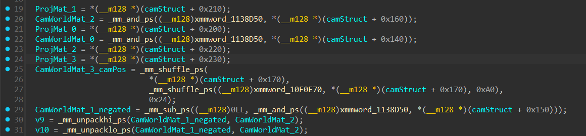
Let’s start by dissecting the instructions in sub_7FD060 which we will rename to “ProjXViewMul” and rename the camera world matrix and projection matrix accessed in this function as CamWorldMat and ProjMat respectively and a1 as camStruct.
Masking Out w with SIMD (Theory)
Let’s start with the first explanation of the SIMD instruction.
The bitmask used in the instruction:
relies on a clever use of NaN values as a bitmask.
xmmword_1138D50 is a static memory address that holds four 32-bit floats:
(NaN, NaN, NaN, 0.0f)
Here specfically ‘NaN’ refer to a 32 bit value where all bits are flipped to 1.
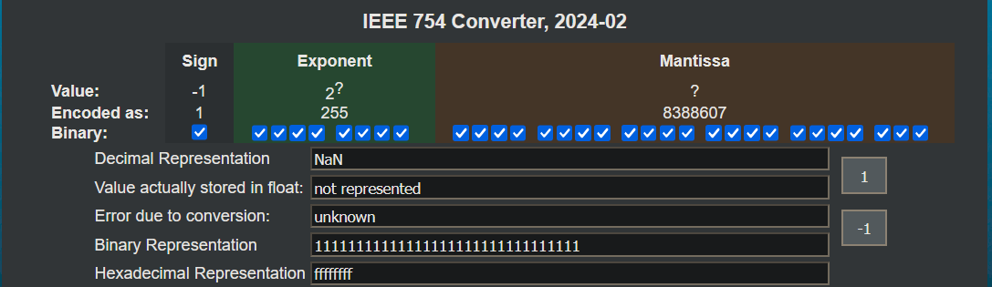
NaN doesn’t literally mean “all bits 1” (0xFFFFFFFF), that’s one specific payload of NaN
As shown above:
- Exponent bits are all 1s
- Mantissa bits are non-zero
- Resulting value is NaN, but its binary pattern is ‘11111111111111111111111111111111’
So, when _mm_and_ps() uses (NaN, NaN, NaN, 0.0f):
- NaN & X,Y,Z = X,Y,Z (because all bits are 1 → preserves input)
- 0.0f & W = 0 (because all bits are 0 → clears input)
Doing this, the bitwise AND preserve x/y/z while zeroing out w.
Next SIMD instruction.
_mm_shuffle_ps (Theory)
Let’s begin with the explanation of the _mm_shuffle_ps function:
Let’s break down _mm_shuffle_ps. It takes two __m128 vectors (a and b) and an 8-bit immediate (imm8) that decides how the elements from
a and b get shuffled into the output.
Let’s denote the result as c. The output vector c is constructed as follows:
- c[0] → element from ‘a’ selected by the lowest two bits of imm8
- c[1] → element from ‘a’ selected by bits 2–3 of imm8
- c[2] → element from ‘b’ selected by bits 4–5 of imm8
- c[3] → element from ‘b’ selected by bits 6–7 of imm8
In short, the immediate value controls which elements from a and b are placed into each position of the result.
_mm_shuffle_ps (Example)
Now let’s walk through and understand a nested _mm_shuffle_ps instruction. Lets start with:
xmmword_10F0E70 is a static memory address that holds four 32-bit floats:
(1.0f, 1.0f, 1.0f, 1.0f)
*(__m128 *)(camStruct + 0x170) is the camera position:
(-112913.16f, -613576.88f, 2234.39f, 1.0f)
The immediate value 0xA0 (in binary 10100000) tells us how to shuffle the inputs.
so output ‘c’ is:
- c[0] -> a[00] , 1.0f
- c[1] -> a[00] , 1.0f
- c[2] -> b[10] , 2234.39f
- c[3] -> b[10] , 2234.39f
In the other shuffle intrinsic is:
0x24 in hex is: 00100100
The final output will be:
- CamWorldMat_3[0] -> (camStruct + 0x170)[00] , -112913.16f
- CamWorldMat_3[1] -> (camStruct + 0x170)[01] , -613576.88f
- CamWorldMat_3[2] -> c[10] , 2234.39f
- CamWorldMat_3[3] -> c[00] , 1.0f
This just seems to give the same vec4. Effectively being CamWorldMat_3 = *(__m128 *)(camStruct + 0x170)
I honestly have no idea why the developers chose to perform these shuffle operations when the final result is already available in memory at camStruct + 0x170. Could be due to legacy code, a byproduct of compiler optimizations, or perhaps a more general-purpose function that handles multiple cases in production. As reverse engineers, we often run into code that appears redundant or overly complex until seen the bigger picture. While it’s tempting to assume we fully understand the intention behind every instruction, sometimes the best approach is to acknowledge what we don’t know and document it and move forward.
Negating a Vector with SIMD (Theory)
The constant xmmword_1138D50 once again holds the values (NaN, NaN, NaN, 0.0f), and is used here as a bitmask just like before.
- (__m128)0LL creates a 128-bit SIMD vector containing all zeros: (0.0f, 0.0f, 0.0f, 0.0f)
- This Effectively does:
- (0 - x, 0 - y, 0 - z, 0 - 0) → (-x, -y, -z, 0)
This SIMD instruction is simply a way to negate a 3D vector while keeping the W component cleared. In the context of a 4x4 camera world matrix this is used to possibly convert handedness.
_mm_unpack (Theory)
The _mm_unpacklo_ps and _mm_unpackhi_ps instructions are used to merge parts of two __m128 vectors
_mm_unpacklo_ps
This unpacks (merges) the lower 64 bits (the first two floats) of both vectors. So it combines the x and y
components of each vector in an alternating pattern.
_mm_unpackhi_ps
Similarly merges the higher 64 bits (the last two floats) of both vectors, so it combines the z and w components in the same alternating fashion.
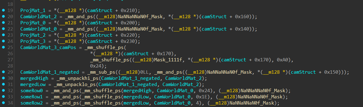
Transposing and Shuffling Intermediate Vectors (Theory)
These SIMD operations perform a fast inverse (We will learn Fast inverse later down the write up) of the camera world matrix by transposing its rotational part and rearranging coordinate components.
- Shuffles components from mergedLow, mergedHigh, and CamWorldMat_0 using _mm_shuffle_ps
- Then masks the result using NaNNaNNaN0f_Mask to zero out the W component (renamed xmmword_1138D50)
Since we’ve already broken down how _mm_shuffle_ps and _mm_and_ps work earlier in this post, we won’t repeat that here.
We will see how it all comes together later down the write up.
Manual Matrix Reconstruction from SIMD Operations (Example)
(This section is for readers who want to understand exactly how the View matrix gets constructed at the instruction level. You can skip ahead to SIMD Matrix multiplication if you’re just here to learn theory)
We’re going to take a snapshot of the memory, walk through the SIMD instructions, and confirm how the final matrix rows are built.
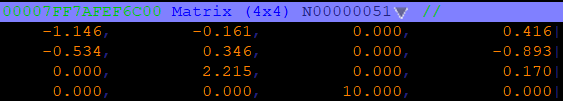
Camera World Matrix
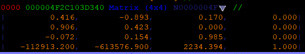
IDA Disassembly
Let’s decode this step-by-step and rebuild the rows of the matrix ourselves to see exactly what’s going on under the hood.
CamWorldMat_0 = [0.416, -0.893, 0.170 0]
CamWorldMat_1_negated = [-0.906, -0.423, 0, 0]
CamWorldMat_2 = [-0.072, 0.154, 0.985, 0]
mergedHigh = [0, 0.985, 0, 0] mergedLow = [-0.906, -0.072, -0.423, 0.154]
First instruction
Binary of 0x24 is ‘00100100’
SomeRow0 =
- merHi[00] = 0
- merHi[01] = 0.985
- CamWorld0[10] = 0.170
- CamWorld0[00] = 0.416
BitMask Applied = [0, 0.985, 0.170, 0]
Second Instruction
Binary of 0x1E is ‘00011110’
SomeRow1 =
- merLo[10] = -0.423
- merLo[11] = 0.154
- CamWorld0[01] = -0.893
- CamWorld0[00] = 0.416
BitMask Applied = [-0.423, 0.154, -0.893, 0]
Third Instruction
Binary of 0x04 is ‘00000100’
SomeRow2 =
- merLo[00] = -0.906
- merLo[01] = -0.072
- CamWorld0[00] = 0.416
- CamWorld0[00] = 0.416
BitMask Applied = [-0.906, -0.072, 0.416, 0]
Let’s keep these Vec4 values in mind, we’ll come back to them shortly.
Before continuing with the manual calculation of the final matrix, let’s take a quick but important detour to understand how matrix multiplication works with SIMD and __m128 vectors.
SIMD-Based Vec4 × 4x4 Matrix Multiplication (Theory)
Matrix Multiplication With a Vec4
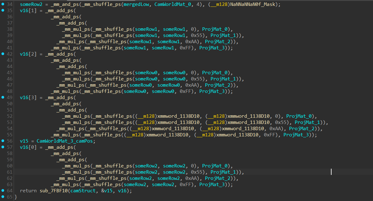
This instruction:
is basically performing a SIMD dot product between a row from the view matrix (someRow1) and each column of the projection matrix (ProjMat_0 … ProjMat_3). Here’s how it works:
Step 1: Shuffle
- _mm_shuffle_ps(someRow1, someRow1, imm) selects one component of someRow1 and replicates it across all 4 slots of a new __m128.
- The different imm values pick different elements:
- 0x00-> picks element 0 (X)
- 0x55-> picks element 1 (Y)
- 0xAA-> picks element 2 (Z)
- 0xFF-> picks element 3 (W)
After shuffling, each __m128 looks like [X,X,X,X], [Y,Y,Y,Y], etc.
Step 2: Multiply with Projection Matrix
- Each shuffled vector is multiplied component-wise with a column of the projection matrix:
- This performs 4 parallel multiplications of the same row component with each element in the projection matrix column.
Step 3: Sum the results
- The _mm_add_ps calls sum all four products together:
(X * ProjMat_0) + (Y * ProjMat_1) + (Z * ProjMat_2) + (W * ProjMat_3)
- The result is a single row of the final View-Projection matrix in SIMD form (__m128).
Step 4: Store the result
- v16[1] now holds the second row of the reconstructed VP matrix.
- This same pattern repeats for the other rows, essentially performing a full matrix multiplication using SIMD instructions.
At a higher level, what this instruction is doing is nothing more than standard matrix multiplication. If we take a row from the view matrix, say [x y z w], and multiply it with the projection matrix, the operation expands like this:
[x  y  z  w]   *  [ projMat00  projMat01  projMat02  projMat03 ]
                  [ projMat10  projMat11  projMat12  projMat13 ]
                  [ projMat20  projMat21  projMat22  projMat23 ]
                  [ projMat30  projMat31  projMat32  projMat33 ]
Which produces:
[ x*projMat00 + y*projMat10 + z*projMat20 + w*projMat30,
  x*projMat01 + y*projMat11 + z*projMat21 + w*projMat31,
  x*projMat02 + y*projMat12 + z*projMat22 + w*projMat32,
  x*projMat03 + y*projMat13 + z*projMat23 + w*projMat33 ]
The results are then added together, producing a new row in the final View-Projection matrix.
This happens for the first three rows (v16[0], v16[1], and v16[2]).
But the last row, v16[3], is a bit different:
Here it uses a constant vector (xmmword_1138D10) which has a value of: (0.0, 0.0, 0.0, 1.0)
Since the first three components are zero, those multiplications with ProjMat_0, ProjMat_1, and ProjMat_2 drop out. The only one left is
is the last one, where w = 1.0 multiplies the row of the Projection matrix.
This effectively copies the last row of the Projection matrix directly into the View-Projection matrix:
The translation from the View matrix is skipped here.
Overengineered Construction:
You might have noticed this is Overengineered.
Here, xmmword_1138D10 is simply (0.0, 0.0, 0.0, 1.0).
When you multiply this constant by the projection matrix rows, only the W=1.0 lane survives, which means you’re
just selecting the last row of the projection matrix (ProjMat_3).
So this whole instruction chain simplifies to:
Just like the camera position shuffle, the final VP row construction is an over-engineered SIMD pattern (probably).
Comparing Constructed Matrix with Camera World Matrix:
- SomeRow0 = [0, 0.985, 0.170, 0]
- SomeRow1 = [-0.423, 0.154, -0.893, 0]
- SomeRow2 = [-0.906, -0.072, 0.416, 0]
- xmmword_1138D10 = [0.0, 0.0, 0.0, 1.0]
Previously v11, v12 and v13 respectively
Let’s recap how it was constructed:
v16[0] = SomeRow2 x Projection Matrix 4x4;
v16[1] = SomeRow1 x Projection Matrix 4x4;
v16[3] = SomeRow0 x Projection Matrix 4x4;
v16[4] = xmmword_1138D10 x Projection Matrix 4x4;
So the Multiplication Looks like so:
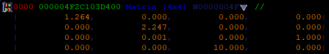
\[\text{NewMatrix} \times \text{ProjectionMatrix} = \begin{bmatrix} -0.906 & -0.072 & 0.416 & 0 \\ -0.423 & 0.154 & -0.893 & 0 \\ 0 & 0.985 & 0.170 & 0 \\ 0 & 0 & 0 & 1.0 \end{bmatrix} \times \begin{bmatrix} 1.264 & 0.000 & 0.000 & 0.000 \\ 0.000 & 2.247 & 0.000 & 0.000 \\ 0.000 & 0.000 & 0.000 & 1.000 \\ 0.000 & 0.000 & 10.000 & 0.000 \end{bmatrix}\]Let’s compare the newly constructed matrix with the original Camera World Matrix to understand how it was derived:
\[New Matrix = \begin{bmatrix} -0.906 & -0.072 & 0.416 & 0 \\ -0.423 & 0.154 & -0.893 & 0 \\ 0 & 0.985 & 0.170 & 0 \\ 0 & 0 & 0 & 1.0 \end{bmatrix}\] \[CamWorldMat = \begin{bmatrix} 0.416 & -0.893 & 0.170 & 0 \\ 0.906 & 0.423 & 0 & 0 \\ -0.072 & 0.154 & 0.985 & 0 \\ -112913.16 & -613576.88 & 2234.39 & 1.0 \end{bmatrix}\]From this comparison, we can see that the new matrix is essentially a rearranged and partially negated version of the Camera World Matrix’s (we found in memory)
Later in Part 4.3 we find the actual Matrix the engine uses for it’s camera transform.
So the Newly Constructed Matrix is constructed like so from the camera world matrix:
- Row[0] from CamWorldMat → becomes Column[2]
- Row[1] from CamWorldMat → becomes –Column[0]
- Row[2] from CamWorldMat → becomes Column[1]
This is Basically doing a Fast inverse for orthonormal Matrices with an additional Coordinate Swap
Keep in mind \(ViewMatrix=(CamWorldMatrix)^{−1}\)
Fast inverse for orthonormal Matrices
If R is a pure rotation matrix meaning:
- No scaling,
- No shear,
- It’s orthonormal (columns are perpendicular and unit-length)
then \(R^{-1} = R^T\)
Let me explain this theory a bit better:
Suppose a 4x4 matrix with homogenous coordinates:
\[C_{world} = \begin{bmatrix} R_{00} & R_{01} & R_{02} & 0 \\ R_{10} & R_{11} & R_{12} & 0 \\ R_{20} & R_{21} & R_{22} & 0 \\ T_x & T_y & T_z & 1.0 \end{bmatrix}\]Here:
- R (upper 3×3) is the orientation of the camera in world space.
- T (bottom row, first 3 values) is the position of the camera in world space.
To get \(C_{world}^{-1}\) we can separate the matrix like so:
\[C_{world} = \begin{bmatrix} R & 0 \\ T & 1 \end{bmatrix}\]and we want its inverse.
The block matrix inverse formula for this special form is:
\[\begin{bmatrix} A & 0 \\ B & 1 \end{bmatrix}^{-1} = \begin{bmatrix} A^{-1} & 0 \\ -BA^{-1} & 1 \end{bmatrix}\](See Wikipedia: Blockwise inversion for the general derivation)
Applying The Formula we get:
- A = R
- B = T
So:
\[C_{world}^{-1} = \begin{bmatrix} R^{-1} & 0 \\ -TR^{-1} & 1 \end{bmatrix}\]Since R is orthonormal (\(R^{-1} = R^T\)):
\[C_{world}^{-1} = \begin{bmatrix} R^T & 0 \\ -TR^T & 1 \end{bmatrix}\]Exponent “T” represents the Transpose and Regular “T” represents the Translation
Now Expand \(−TR^T\) into its dot products:
if:
\[R = \begin{bmatrix} R_{0x} & R_{0y} & R_{0z} \\ R_{1x} & R_{1y} & R_{1z} \\ R_{2x} & R_{2y} & R_{2z} \\ \end{bmatrix}\]and \(T = [T_x, T_y, T_z],\)
So:
\[-TR^T= \begin{bmatrix} -T_x & -T_y & -T_z \\ \end{bmatrix} \times \begin{bmatrix} R_{0x} & R_{1x} & R_{2x} \\ R_{0y} & R_{1y} & R_{2y} \\ R_{0z} & R_{1z} & R_{2z} \\ \end{bmatrix}\]then:
\[-TR^T = [-dot(T,R_0), -dot(T,R_1), -dot(T,R_2)]\]So the last row becomes:
\[[-dot(T,R_0), -dot(T,R_1), -dot(T,R_2)]\]And Expanding \(R^T\) is just the Transpose of the Rotation, thus completing the inverse:
\[C_{world}^{-1} = \begin{bmatrix} R^T & 0 \\ -TR^T & 1 \end{bmatrix}\]Here for the last row the engine does another method (which we will reverse in Part 4.3):
They take Negated LastRow of \(C_{world}\) (Translation) and multiply it with View Matrix without Translation and add the calculated output into the last row.
This is mathamatically the same as:
\[-TR^T = [-dot(T,R_0), -dot(T,R_1), -dot(T,R_2)]\]No i wont show proof, do it yourself and confirm
The only difference seen in this Engine is that they also do:
- A Coordinate Swap.
- Changes Handedness.
⚠️ Note:
This fast inverse only works for rigid transforms (no scale/shear). For a general 4×4 matrix you must use:
\(\begin{align}M^{-1} = \frac{1}{det(M)} adj(M)\end{align}\)
Continuaton of Manual Matrix Reconstruction (Example)
Now that we know how SIMD-Based Vec4 × 4x4 Matrix Multiplication works let’s continue the Matrix Reconstruction.
- SomeRow0 = [0, 0.985, 0.170, 0]
- SomeRow1 = [-0.423, 0.154, -0.893, 0]
- SomeRow2 = [-0.906, -0.072, 0.416, 0]
Lets construct v16[0] as an example:
After Shuffling:
_mm_mul_ps( [-0.906, -0.906, -0.906, -0.906] , ProjMat_0),
_mm_mul_ps( [-0.072, -0.072, -0.072, -0.072] , ProjMat_1)),
_mm_mul_ps( [0.416, 0.416, 0.416, 0.416] , ProjMat_2)),
_mm_mul_ps( [0, 0, 0, 0] , ProjMat_3));
For reference, The Projection Matrix:
After Multipling:
v16[0] = _mm_add_ps(
             _mm_add_ps(
               _mm_add_ps(
		[-1.145, 0, 0, 0]
		 [0, -0.161, 0, 0])
		   [0, 0, 0, 0.416])
		    	[0, 0, 0, 0])
After Addition:
v16[0] = [-1.145, -0.161, 0, 0.416]
Confirmation Of VP Matrix:
Here we see the 0th row of the VP matrix matches exactly as our manual reconstruction of the row.
Passing the Results Forward
return sub_7FBF10(camStruct, &v15, v16);
Now that the function has finished constructing the ViewProjection matrix (without translation), it makes its final call:
- &v15 = (camera position)
- v16 = (ViewProjection matrix without translation)
The sub_7FBF10 function constructs the View-Projection Matrix with Translation.
Why use View-Projection Matrix without Translation?
That’s usually for the skybox.
If the camera’s position (translation) was applied, the sky would “move” as you walk around, By removing translation, the skybox always stays centered on you, and only rotation matters
That wraps up the partial View-Projection matrix construction. In the next post, we’ll look at sub_7FBF10, the function that builds the full View-Projection Matrix.