Part 5.1: Reversing Construction of the Projection Matrix (X & Y Scales)
Now that we have found the function responsible for constructing the Perspective Projection Matrix Let’s begin reversing it to have a clear understanding on how the game engine constructs this matrix every frame!
Now we wont be reversing the entire function which we have stumbled into because the function we found by “finding out what writes to this address” feature in CE seems to be a very large function responsible for constructing various Matrices such as Camera, View, Projection, Inverse Projection, Identity Scaler, ViewProjection, InvProjCamera and has multiple function calls to Matrix4x4Multiply(), Matrix4x4Inverse() and even Calculate View Frustum function. We will only be looking into Projection and Inverse Projection Construction.
Let’s look at where we were initially:
The highlighted block is the First Row of the Projection Matrix which is the instruction responsible for updating our Projection Matrix every frame. let’s zoom out a bit and see what’s really going on.
It seems to be a part of an if-else block where our instruction is being executed inside the else block.
else block:
if block:
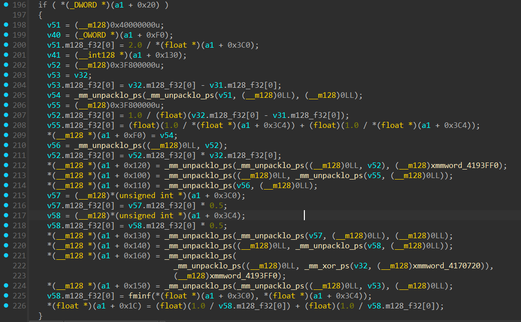
Now we clearly see the big picture happening here, The else block is clearly constructing a Perspective Projection Matrix as per my reasoning in part-4. The if block seems to be constructing an Orthographic Projection Matrix, my reasoning being these lines:
and
The values inside
a1 + 0x3C0anda1 + 0x3C4have been checked to be Width and Height using CE during runtime.
These are the expected xScale and yScale values for an Orthographic Projection matrix. And look where it is stored:
and
But what the hell is an _mm_unpacklo_ps??
The basic theory is simple:
the “lo” in “unpacklo” means we are only targeting the lowest 64-bits inside a 128-bit register and “ps” stands for “Packed Single” which tells the cpu to treat the 128-bit register as four 32-bit floats.
This is basically what it does:Suppose:
Register A: [ A3, A2, A1, A0 ] (where A0 is the lowest float) (arg1)
Register B: [ B3, B2, B1, B0 ] (arg2)Result:
[ A0, B0, A1, B1 ]
that’s all.
As a refresher, a standard Orthographic Projection Matrix looks like this:
\[\begin{bmatrix} \frac{2}{w} & 0 & 0 & 0 \\ 0 & \frac{2}{h} & 0 & 0 \\ 0 & 0 & \frac{1}{z_{far} - z_{near}} & 0 \\ 0 & 0 & -\frac{z_{near}}{z_{far} - z_{near}} & 1 \end{bmatrix}\]Thus validating our belief that the if block is constructing an Orthographic Projection Matrix so the if-else logic would be:
Now for the hard part, Reversing the complete logic inside the else block…
Reversing Construction of the Perspective-Projection Matrix
Let’s begin Reversing the else block:
xScale Construction:
Because the compiler interleaved the instructions for optimization, the calculation for the X and Y scales are tangled together. Let’s isolate just the xScale logic:
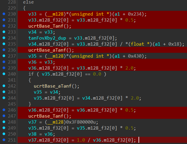
Lines highlighted in red are responsible for xScale calculation.
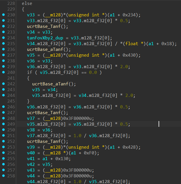
Let’s start with this block
Using CE for dynamic analysis we can see that (a1 + 0x234) is FovX in radians or “1.8326” matching our Fov slider we set to “105 degrees” before.
It loads it as an (__m128)*(unsigned int *) which treats it as an integer but we know it is a float, it doesn’t matter what type it is as long as it’s 4 bytes. At the CPU level,
bits are just bits…
So basically load a FovX in radians into “v33” then immediately divide it by 2 so now “v33” holds the value fovX/2.
Next we see a call ucrtBase_Tanf(); which IDA has failed to assign arguments to. But no worries we will look at the assembly for it’s arguments.
Following Windows ABI convention xmm0 will have the arg and result will be stored inside xmm0 as well. Tracing the assembly we see:
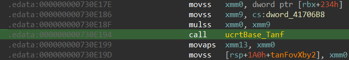
[rbx+234h] is our fovX which gets stored into xmm0, gets multiplied by 0.5 and used as an arg for tanf call. After the call the lowest 32-bits of xmm0 register will hold tan(fovX/2).
After this block there are lines which use FovX which i have not highlighted. This is because its either trying to derive FovY with FovX or is saving the current value of v33 for later use.
Next block is:
Moving onto the next line we see redundancy or a quirk, it is an ucrtBase_aTanf(); call and looking at the assembly the argument is v33 again so now “v33 = atanf(tanf(fovX/2))” which will equal “fovX/2”.
Why?
FovX can only have a value from 60 to 120 degrees in-game. Since we divided it by 2, the angle is between 30 and 60 degrees (well within the -π/2 to π/2 principal bounds of arctan), meaning arctan(tan(x)) = x. Calling a atanf function just to get back fovX/2 is a waste of CPU cycles but still negligible.
The identity arctan(tan(x)) = x holds if and only if x lies strictly inside (−90°, 90°), the identity holds without exception.
then:
v36 is initialized with the value of v33 (fovX / 2) and immediately multiplied by 2.0, bringing it back to the original fovX
Next block is:
v36 was fovX, now its fovX/2 after “v36 * 0.5”.
Then it calls a ucrtBase_Tanf() with arg as v36 so the result in v36 is tan(fovX/2).
Next it saves tan(fovX/2) into v38 for later calculations and finally does “v37.m128_f32[0] = 1.0 / v36.m128_f32[0];” Completing our calculation for xScale and saving it inside v37.
\[x_{scale} = \frac{1}{\tan{\left(\frac{Fov_X}{2}\right)}}\]yScale Construction:

Let’s start with this block:
v34 is first assigned the value of tan(fovX/2) (as an m128 so only lowest 32 bits are fov values) then later is divided by a value at *(float *)(a1 + 0x18). With dynamic analysis we
can see it is a constant of “1.777” which is our aspect ratio of 16:9 but the interesting part is that it’s constant and won’t change even when aspect ratio is 4:3 or 16:10.
So now v34 holds the value “tan(fovX/2) / Aspect Ratio”, Hmm this formula looks familiar…
\[\tan\left(\frac{FOV_X}{2}\right) \,/\, A = \tan\left(\frac{FOV_Y}{2}\right)\]In the next line a value from (__m128)*(unsigned int *)(a1 + 0x430) is loaded into v35. With dynamic analysis we can see most of the time this is zero.
Next block:
if (__m128)*(unsigned int *)(a1 + 0x430) / v35 is zero then it will calculate the value of FovY using FovX with this formula:
and save it inside “v35”
v34 previously held the value of “tan(fovX/2) / Aspect Ratio” so now after the ucrtBase_aTanf() call with its arg being “v34”, “v34” will have the value
atan(tan(fovX/2) / AspectRatio)). This gets saved into v35 and immediately after multiples v34 with 2 and saves it inside v35. So now v35 has the value:
“2 * atan(tan(fovX/2) / AspectRatio))” matching our formula exactly!
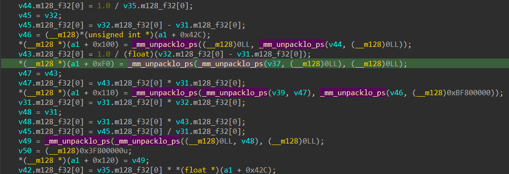
Next block:
Next it will calculate FovY/2 and save it into “v35” then save the value of “v35” into “v42” for later calculations.
Then it finally does a call to ucrtBase_aTanf() with “v35” as arg so the value inside “v35” is tan(fovY/2), Next it will complete the calculation for yScale by doing:
v44.m128_f32[0] = 1.0 / v35.m128_f32[0]; so final value inside “v44” is “1/tan(fovY/2)”
So now v44 = 1/tan(fovY/2) and v37 = 1/tan(fovX/2) (Only the lowest 32-bits are used, rest are 0’s).
Putting It All Together: The Cleaned Code
Now that we understand the math behind both the X and Y scales, we can go back into IDA, rename our variables, and comment the IDA pseudo code.
Since this part is getting too long the reversal for depth mapping calculations will be done on the next part!
In Part 5.2, we will look at how the engine uses zNear and zFar for depth mapping, and how it uses SIMD instructions like _mm_unpacklo_ps to pack all of these isolated variables into the final 4x4 projection matrix in memory.